Doing some more weathering on the robot. Got it looking pretty good in the skirt/foot area so far:
Also doing a little metal drybrushing to reveal the "metal" underneath (okay, wood, but shhh...!)
Even did some test brushing on my old proton pack. Really adds something to it, I think.
Wednesday, October 21, 2015
Thursday, October 15, 2015
mud, blood, and crud
Playing with some acrylic washes now, experimenting with different shades and thicknesses of red, brown, and gray. You can see some light stuff in the washes here, and also some bis where I caked it on relatively heavy.
(Note the "corrosion" in the joints of the power coupler on the right, the brown streaks. And also the accumulated dirt in the coin return on the left.)
Wednesday, October 14, 2015
More weathering
So I'm using the back maintenance hatch as a sort of "guinea pig" for my weathering efforts. Tonight I'm experimenting with color washes, dilute paint solutions that are dabbed on and then wiped way with a damp paper towel. Going for a subtle effect, just making it look like it's been around a bit, you might say.
Tuesday, October 13, 2015
R2 Part II: the adventure continues
So what does one do once one has a nice, shiny new R2? One commences dirtying it up, that's what one does. I'm experimenting with different techniques on the internet. First, a bit of rust paint leftover from some previous weathering attempts, just gunked on to look like a nasty corrosive spot:
Sunday, October 11, 2015
I did it.
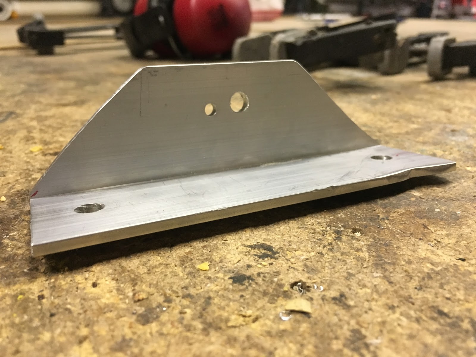
OK, so the bracket from yesterday didn't quite work, as the angle made it push the shell up at an awkward angle, so I fabbed up a new bracket, with the ankle mount hold up higher. This gives it a bit more wiggle room, so to speak.
Anyway, once that was on, there was nothing left but to put the side panels on (gorilla tape, just in case I need to take 'em off again), and that was it:
Woo-hoo! Got it. Very pleased, can't wait to show it off. One week shy of ten months, start to finish. Lookin' good.
Actually, lookin' a little too good... (ominous foreshadowing)
Anyway, once that was on, there was nothing left but to put the side panels on (gorilla tape, just in case I need to take 'em off again), and that was it:
(cue Star Wars music)
Woo-hoo! Got it. Very pleased, can't wait to show it off. One week shy of ten months, start to finish. Lookin' good.
Actually, lookin' a little too good... (ominous foreshadowing)
Saturday, October 10, 2015
Center foot redux
OK, remember when I "sewed" the temp foot drive on the center foot with wire? Yeah, that sucked. It's too loose and has a tendency to fall backwards if I try to reverse, plus it's tiled at a bad angle. So instead I'm going to do it a bracket just like the other feet.
Note the "damage" on the flat part closest to the camera. That's actually intentional; the bolts on the front wheel mount are kind of close quarters, so I had to notch this section out so that the bracket would lay flat against it.
Friday, October 9, 2015
Getting ready to mount right foot
OK, so I didn't have a picture of my mounting the drive to the bracket before, so here you can see how it looks on the right foot. It's a little crooked, but it slips on OK, so it's all good:
Of course, I can't attach the drive to the bracket until the bracket & foot shell are all done getting mounted to the ankle bracket, so we'll do that first:
Wednesday, October 7, 2015
Right foot staging...
Got the right foot assembled, and ready for installation:
BTW, the hose is just regular copper braiding that has been "filled in" with vinyl tubing to give it bulk. I also taped down the ends and glued 'em into the receptacles on the battery box but they're friction-mounted on the foot shell side, in case I need to disassemble them for whatever reason.
Tuesday, October 6, 2015
Left foot complete
Once I was satisfied the bracket would work, I went ahead & drilled some holes going through the bracket into the motor drives. I then lock-tited some bolts sticking up through the holes in the drive so I could lower the bracket down onto them and secure them with lock nuts. It came together quite nicely:
(notice also I got the foot hoses attached, yay :)
Here you can see the complete left leg assembly (except the side panel, which I'll attach last) and the right leg, still using the temp wooden bracket. Getting close.
Monday, October 5, 2015
Rear foot shell mount test
So I took the metal bracket I made the other night home and bolted it to the ankle with the foot shell inside. As you can see, it fits nicely, and I was able to get the bolt threaded in and everything. I do believe this will do the trick.
Saturday, October 3, 2015
Rear foot-shell mounts
After talking to some local club members, I decided to mount the foot shells using some angled aluminum cut to shape. It's basically a 3' long bit of aluminum bent into an L with 1-1/2" length for each "leg". So, I got some at the Home Depot, and went to Hammerspace to commence cutting & drilling:
First I cut to size and trimmed at a 45-degree angle so it would fit within the shell:
Then I took it home and marked a pilot hole for where the bolt goes through the ankle:
And then I took it back and drilled that through:
This should hold the drive very securely to the ankle, but still provide enough room for me to work in the securing bolts, knock wood.
Subscribe to:
Posts (Atom)