In the meantime, I got out all the "thrust vector actuators" and gave them nice paint jobs, as seen below. Unfortunately, I couldn't match the color quite with what I was using on the main hull, but eh.

Here, btw, is the look I'm going with for the hull:

Now, to business: first thing I do is glue down the actuators (see below). Next, there are four pairs of pieces as shown below:

They get glued together to make stabilizers, like so:


Next up are the two Y-shaped braces, which go to either side of the central actuator:

Now, let's add a little more weathering...

Now, it's time to dig out some tiny pieces from past issues. First, there's these two little guys from issues 44 & 46, which go on either side of the rear engine assembly. The photo in the magazine isn't horrendously clear, so I've zoomed in:


Now comes these four parts (careful, the middle one is delicate as hell):

The two top bits go in right as shown...

The bottom saddle fits into the slot provided.

And the W-shaped bit goes on top of them.

For the next two parts, we need to go and look for these two holes on the parts immediately forward of the central turret area:

These A-frame structures are added here, with the legs going into the holes we just found.

To each side of those, we add these tiny little pipes.
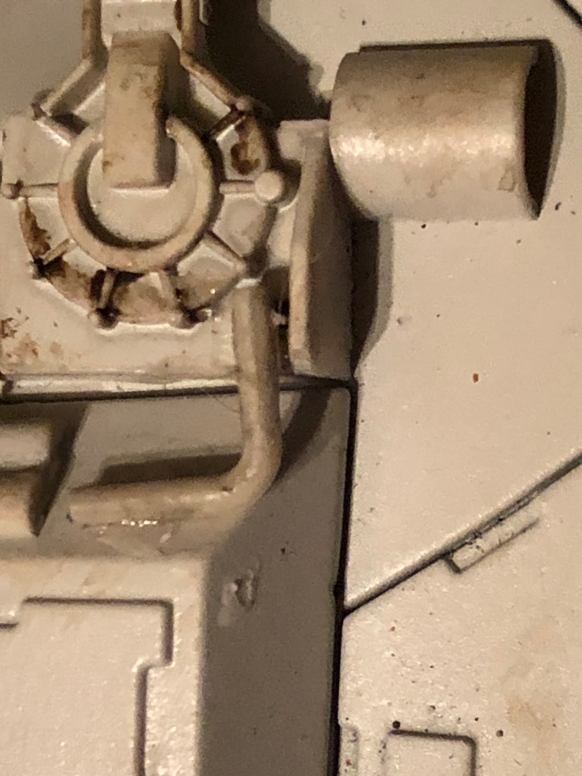
And finally, the larger L-shaped pipes get added aft of the turret.

And that's it for that! Hopefully we can pick up the pace a bit now that the main paintjob is done. Looks like some interesting stuff ahead!
.
No comments:
Post a Comment