Showing posts with label electronics. Show all posts

Tuesday, January 16, 2018

Issue 87

OK, so exciting this time, we're adding the landing lights.

First up, plug in the battery box to the circuit board like it was when we were working on the gangplank.


Now, we'll be using these 5 cables: 2 long yellow cables, 2 shorter ones, and the gray one from this issue.


First, one shorter cable gets bolted into the port rear light, and plugged in to the position shown.


Next, the port forward landing light, plugged in right next to the other one.


Now, the starboard rear light...


And, the starboard forward light.


Last, the gray wire gets plugged into the spot shown. This is one of the landing gear recesses, because we want the lights to work when the gear is down.
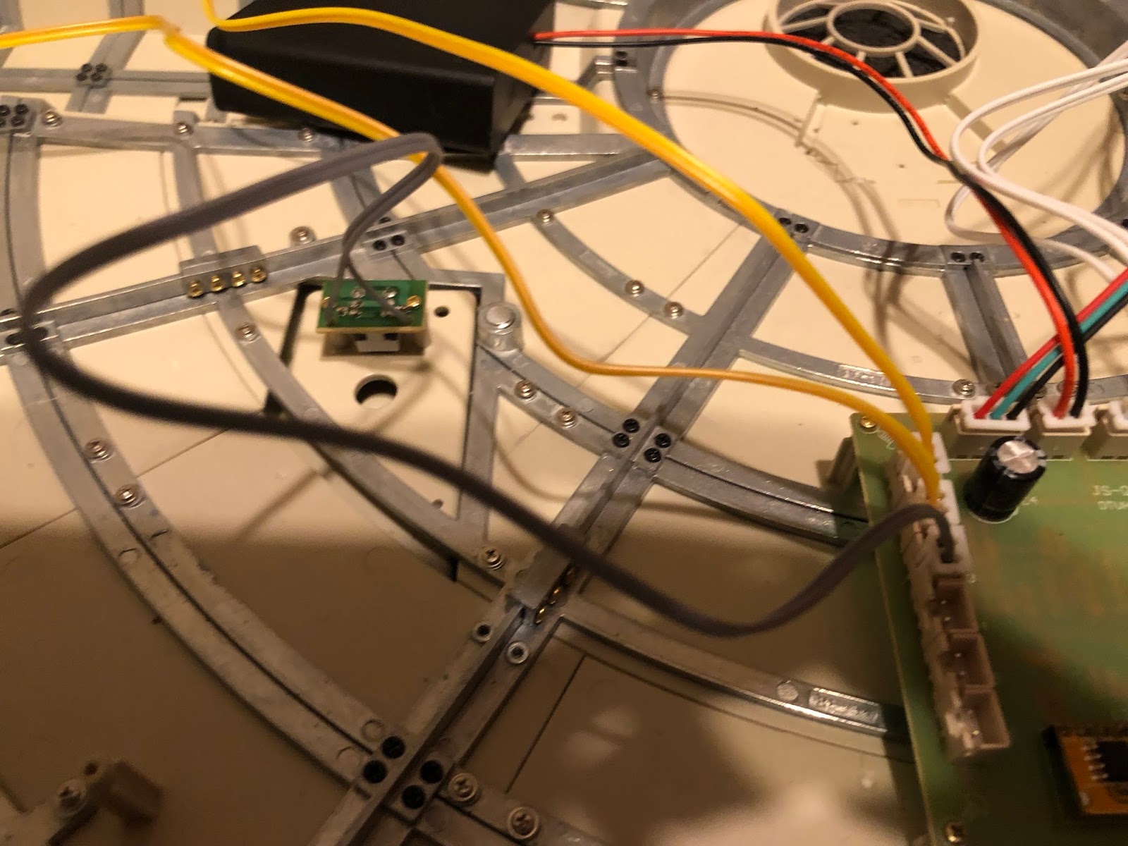

To test, do the following:

  1. Turn on the battery box.
  2. Turn on the PC board. You should see a red light.
  3. Hold down the button in the landing gear recess we just installed.
  4. While doing that, push the "B" button on the PC board.
I would take a picture, but..well, both hands occupied with the buttons.

Anyway, that's done. Time to move on.

Wednesday, October 11, 2017

Issue 57

Okay, big week this time around! We get to add in the electronics and test the gangplank!

First up, in goes the circuit board on the four posts in the back:


Now, we poke the little rubber "plug" for the power port out (on yours this is probably camouflaged with black "damage". I cleaned mine up--whoops!) Just push the "ring" end up and into the interior.


The ring goes around the post shown, and one of the short silver screws with the wide head is used to secure it.


Next, the port itself is attached. Make sure it is lined up so that the port is right over the hole, as shown here.


Two of the long golden screws will do this.


Now, remember how they said not to bolt down the battery box to the frame just yet? Yeah, here's why. Go ahead & plug it in to the port shown.


Next to it goes the power connection we just added.


After that, the motor connection to the gangplank.


And finally, the gangplank lights.


Power on the battery box, and find the blue switch in-line from the power connection. Turn it on, and you should get a red light on the board...


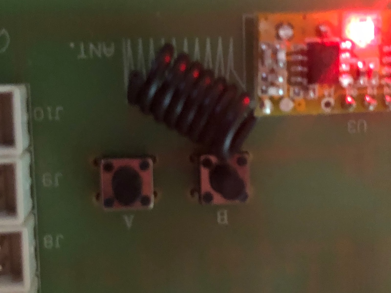
Note that the board has two buttons on it, A and B. B tests lights we don't have installed yet, but A should test the gangplank. Give it a shot.


If all goes well, you should get this...


NOTE: It may happen that your gangplank goes down and then keeps trying to go down. In which case, look at the top of the motor for the two paddles and the white "hook", shown here:


Essentially, the problem is that the top paddle should be carried down by the white hook until it makes contact with the lower paddle, which stops the ramp descent. Make sure it's tucked in under the hook, like so.


Anyway, that's it for this time. Cool stuff.

Sunday, March 8, 2015

Installing PADAWAN

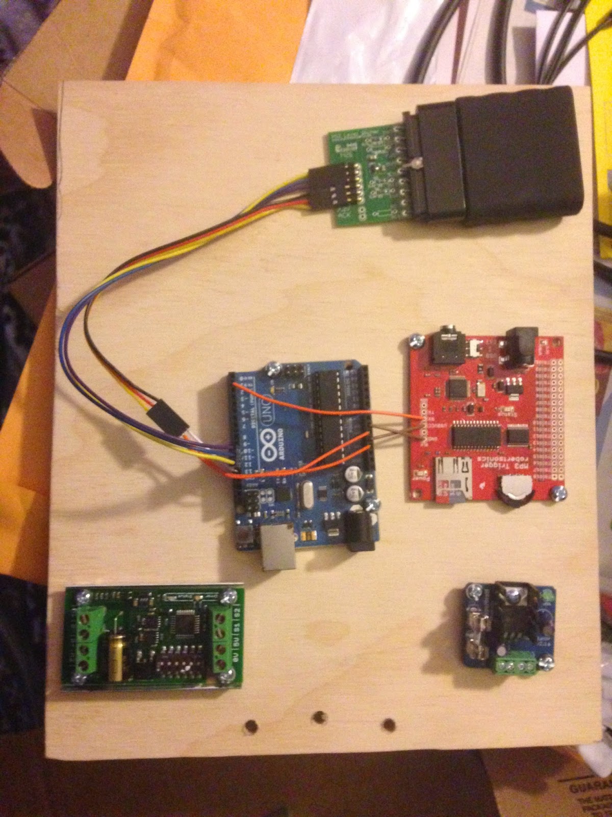
So I have been working on getting the PADAWAN system installed as much as possible for Planet ComiCon. First things first: I need a motherboard to mount all the different pieces to, so they're not just floating around inside the robot body or something. Also some way of getting to them easily. Based on some pictuers I've seen of someone else's build, I've decided to go with a wooden panel that can fold down once the rear door is removed. So, I picked up some wood at the store and cut it to about an 8x10 rectangle, and added my first few components, thus:


From top to bottom that's the playstation 2 remote control receiver, the arduino that runs everything (in blue), the mp3 player (in red), the motor driver for the dome motor (on the left) and the 5V regulator for the dome lights and speaker (on the right). Since the battery is 12V, I need to run it through the voltage regulator to feed the dome lighting system.


Incidentally, here you can see the slip ring in the middle of the dome which feeds the power up. You can see I've attached a small quick-connect plug on the end there, and bundled up the wires so they're not kicking around all over the place.


And here's the motherboard bolted inside the R2 unit. There's a hinge n the back so it will fold down, and I'm using velcro tie-downs to hold it up. The shot is a little dark, but you can see a lot of wires going up the right-hand pole to the dome motor, dome lights, and speaker (the black rectangle in the top foreground). It's one of those USB powered ones, so since USB is a 5v draw, I was able to put it in with the dome lights downstream from the regulator. Kind of a pain though, as once I snipped off the USB plug, the actual power wires within were very tiny, maybe 24-26 gauge.


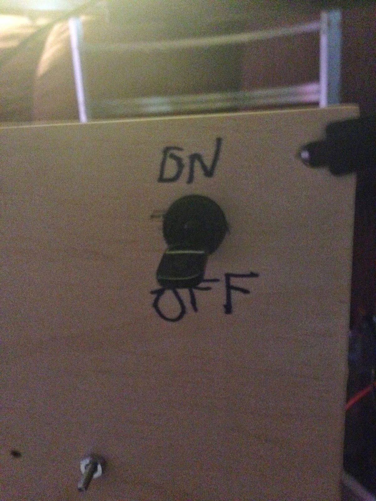
On the back I mounted a big ol' power switch (I'm actually going to have to replace it with a DPDT (double-pole, double-throw: that means I can turn two circuits on at once) switch later, as I'll want this to toggle both the 12V and 24V circuits at the same time. The 24V circuit will be strictly for the foot motors, actually moving this sucker around).


And here's R2 on his brand new handtruck, ready for his debut :)

I think this week I might get back to 3-D printing body parts. After the con I'd really like to tackle as much body stuff as possible,and work on getting the legs together. Then snag some skins as soon as a set show up, and after that... I gotta figure out how to move this sucker around.

Oh, boy.