Showing posts with label teeces. Show all posts

Sunday, March 8, 2015

Installing PADAWAN

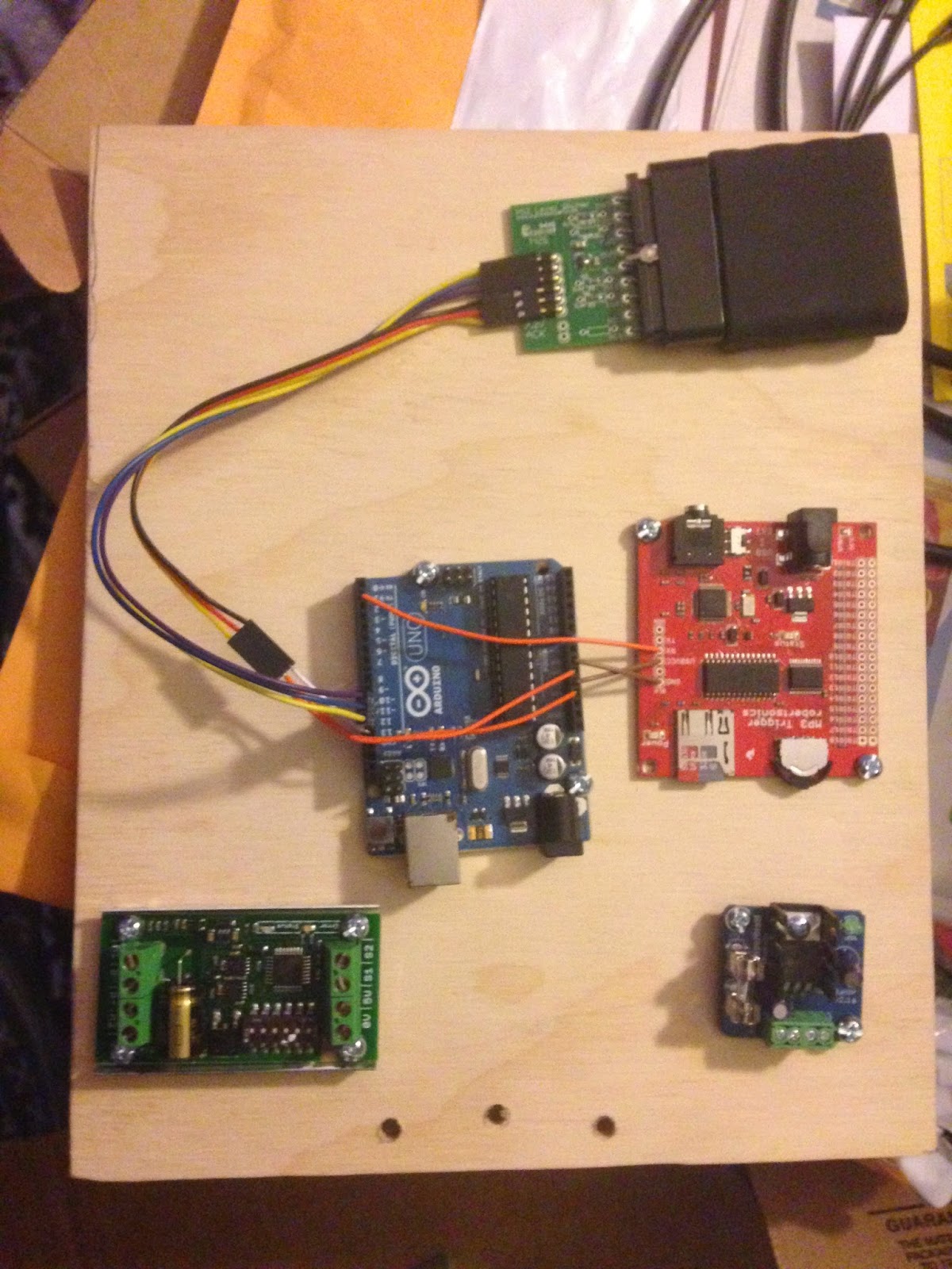
So I have been working on getting the PADAWAN system installed as much as possible for Planet ComiCon. First things first: I need a motherboard to mount all the different pieces to, so they're not just floating around inside the robot body or something. Also some way of getting to them easily. Based on some pictuers I've seen of someone else's build, I've decided to go with a wooden panel that can fold down once the rear door is removed. So, I picked up some wood at the store and cut it to about an 8x10 rectangle, and added my first few components, thus:


From top to bottom that's the playstation 2 remote control receiver, the arduino that runs everything (in blue), the mp3 player (in red), the motor driver for the dome motor (on the left) and the 5V regulator for the dome lights and speaker (on the right). Since the battery is 12V, I need to run it through the voltage regulator to feed the dome lighting system.


Incidentally, here you can see the slip ring in the middle of the dome which feeds the power up. You can see I've attached a small quick-connect plug on the end there, and bundled up the wires so they're not kicking around all over the place.


And here's the motherboard bolted inside the R2 unit. There's a hinge n the back so it will fold down, and I'm using velcro tie-downs to hold it up. The shot is a little dark, but you can see a lot of wires going up the right-hand pole to the dome motor, dome lights, and speaker (the black rectangle in the top foreground). It's one of those USB powered ones, so since USB is a 5v draw, I was able to put it in with the dome lights downstream from the regulator. Kind of a pain though, as once I snipped off the USB plug, the actual power wires within were very tiny, maybe 24-26 gauge.
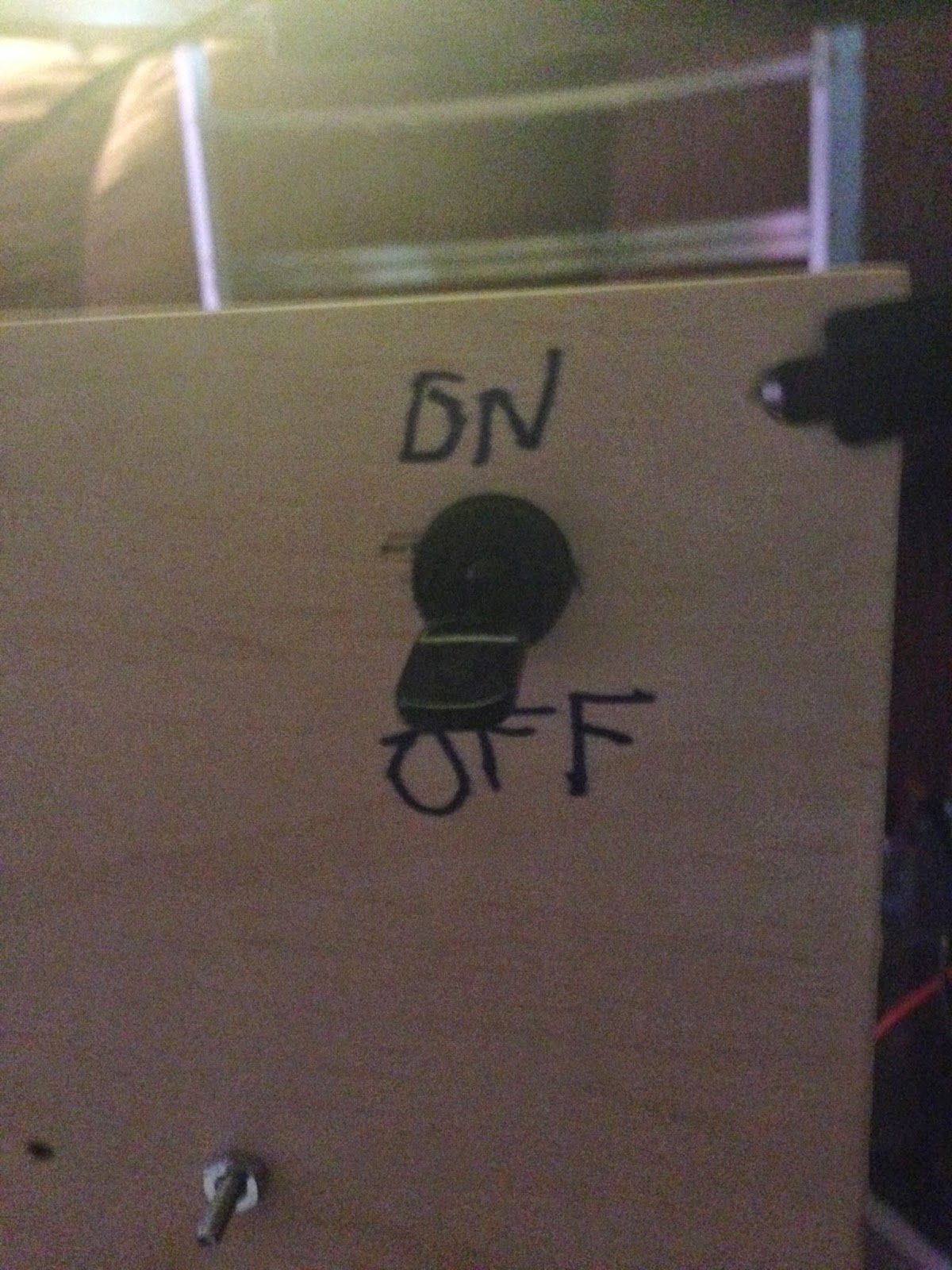

On the back I mounted a big ol' power switch (I'm actually going to have to replace it with a DPDT (double-pole, double-throw: that means I can turn two circuits on at once) switch later, as I'll want this to toggle both the 12V and 24V circuits at the same time. The 24V circuit will be strictly for the foot motors, actually moving this sucker around).


And here's R2 on his brand new handtruck, ready for his debut :)

I think this week I might get back to 3-D printing body parts. After the con I'd really like to tackle as much body stuff as possible,and work on getting the legs together. Then snag some skins as soon as a set show up, and after that... I gotta figure out how to move this sucker around.

Oh, boy.

Thursday, January 29, 2015

Dome: complete

So tonight was the night to finish work on the dome. I mounted the lights inside the dome, and got everything together. There's a coupe of little bitty details, but I'm basically rocking.


I made a couple of these as mounts/diffusers for the front and rear PSIs. This one is the rear.

Here you can see the one for the front PSI. The diffuser is hot glued to the MDF ring; the blue tape is holding the PSI in place inside it.


Unfortunately (as you see here) I had accidentally put one of the ring holes right where the rear PSI is,so I had to attach the rear diffuser to the dome instead of the MDF ring. I'm using paint tape here, but that's just a temporary measure until I get some more permanent mount. Like duct tape.


It's all good, though. It came out looking nice:


Here, you can see the rear assembly. From left to right: rear PSI, rear holoprojector, rear logic display, and battery pack velcroed to the MDF ring so I can pop it off when I need to swap out the batteries.


The front assembly:  cable from rear logic display, the front logic displays, the front PSI, and front holoprojector.


Rear view:


Front view:


And here's a video of it in action:


So, that's the dome. Not sure what's going to be next. I've got the frame coming, and will be getting a set of legs before long. I may just rest until they show up, concentrating on more 3D printing, but I'm nearly there. I might also do the skins, laser cutting them at the maker space. In any case, this is a pretty big milestone considering I only started about six weeks ago. In any case, I'm having a blast.

Monday, January 26, 2015

let there be more light

So this evening I sat down to do the Rear Logic Display. I figured I'd get 2 rows done, maybe. I somehow managed to get 4. I was waiting on a print of my first attempt at a 3d printed diffuser for the front and rear PSIs, so I went ahead and kept on soldering. I would have got all 5 rows, but I goofed in putting an LED in the wrong way so I had to take it out and unplug the holes.

Lessons learned:
  • double-check the pins before you solder.
  • If you have to remove one, use the iron to melt the solder and take it out a little at a time.
  • If you have solder in a hole, put a little solder in it and get it all nice and liquid then tap it on a flat surface (I had missed the bit about adding a little extra solder when the guy at the makerspace showed me the other night)
  • DO NOT hold the iron to the hole in hopes of melting it out, as you may well gunk it up and destroy the connection. I now have one LED that won't light up anymore because of this.
 Anyway. Other than that one bulb, it's all good. I tried the diffuser, and found that A) it blocks too much light, B) the inside radius is too big--I want the PSIs to fit snugly inside, and C) It's too shallow. I want it to tuck in there nicely. I'll redesign and print again tomorrow night. Fortunately, Autocad 123D is proving to be very simple to use, and even exports straight to STL. It's not perfect, but whaddya want fer nothin'?

Anyway, got home and was disconcerted to find that the lights wouldn't work. Funny thing. The chain with the rear PSI was fine. But the one with the FLDs and front PSI was kaput. It was either all-on or all-off. Taking instruction from the FAQ, I removed and reseated a few of the LED controllers, which didn't help, then reseated the Arduino Pro Mini, which did. So thank goodness for that. It's pretty impressive.. can't wait to show it off. Hopefully tomorrow.

Sunday, January 25, 2015

let there be lights

So this was an interesting weekend, alternatively fustrating and productive, with lessons learned and progress made. I'm well on the way to a completed dome.

First off, as mentioned Thursday, my LED controllers and jumper wires showed up. So Friday after a long, frustrating day at work I sat down to try to program my Arduino Pro Mini with the standard Teeces sketch as found here. Now, I had originally thought to use a Pro Micro because it has the built-in USB, but it turned out that it's a little too big, with extra bits hanging over the side on both ends. Not a problem in and of itself once you adjust the pinouts in the code, but it did butt up against the screw-down terminals for the power connection, meaning it wouldn't be a snug fit in the socket. So I bit the bullet and got a mini and FTDI adapter at the local MicroCenter.

So if you haven't done one of these before, you basically go with a USB cable to a little PCB that is essentially a USB jack on one side and 5 or 6 pins on the other. Mostly 6 these days, which is good. You connect it to the pins on your Mini, and that dumps the code and all that down. Unfortunately, it would not work. I tried different computers, different serial drivers, different settings...all to no avail. I posted for help on the arduino forums, no help there. Saturday morning, I woke up, and went at it again...and I got it. My mistake? I had assumed the FTDI & Pro Mini should be both "right side up" when connected together, but the pinouts, upon closer examination, showed otherwise. I turned the Pro Mini upside down relative to the FTDI, and glory be. We have liftoff.

Once that happened, I dropped the LED controllers into their sockets and put a few test LEDs in without soldering. Bingo. Random flickerage. So after my volunteer shift I went to the makerspace and got to soldering on the Front Logic displays. There's two of them with 45 LEDs each. I'd already done the front and rear PSIs, which use nice big 5mm LEDs, but the 3mm for the rest of the displays were quite a different task. Lots of close, careful work.

A couple of times I messed up, getting solder in a hole before I could put an LED in. I learned two ways this weekend of dealing with that:
  1. Use the tip of the iron to melt the solder and then give it a sharp rap on the table. This should jar it loose. Not recommended if you ahve delicate stuff soldered to the board already.
  2. Poke at it with the component that needs to go in from one side, and heat it with the iron from the other. Then just ease the component in and solder it the rest of the way.
Anyway, Saturday and Sunday I did one front logic display each, and with the PSIs connected I had 4 out of 5 lights working. That's a total of 144 LEDs soldered. That just leaves the Rear Logic Display... 135 LEDs. Oy.


Funny thing. You may notice in the picture that the rear PSI is mostly yellow but has a little green. Sometimes on the PSIs, the color doesn't change all the way, just most of the way like that. I need to see if that's something people have been seeing before or what. In any case, I'm not too worried about it for now.

In the meantime, I glued in the holoprojectors to the dome. I tried using my super glue first, but it didn't last. Then I tried the glue gun today, but it was surprisingly ineffective. The owner of the makerspace said it was probably because I was using the small, low-temperature glue guns and to use one of the big high-temperature ones instead. That did the trick. At least, it has so far. So, another lesson learned. Oh, and I sanded off the paint from the bits where the glue was going, to give it something more to hang on to.

Anyway, got the word from the frame guy to send the balance. So I'll do that tomorrow if I can. Good timing, n'est-ce pas? And then tomorrow night I'll start to soldering the RLD. I'd like to have that done sometime this week so I can secure it and the battery pack (4xAA from Radio Shack) inside the dome. I still haven't added any kind of external switch; I'm waiting to see how the rest of the droid electronics pan out.  But in any case, I will have a fully done droid. Just gotta get a gear for turning it anddrop that in there, and I'm golden. Cool beans.

Thursday, January 22, 2015

Dome final details and Teeces LEDs

Long day at work today, real pain in the neck. Right back to it tomorrow, but in the meantime got some good progress on the R2.

First off, I started printing more of the battery harness assemblies, got the last 3 done. Since it was open house, I brought the dome and put it up to show off. While the prints were going, I busied myself soldering the front and rear PSIs:


All nice and done. Then I glue-gunned the MDF ring inside the dome, and then added the "pie slices" and the mounting rings for the holoprojectors. Here's one with the projector mounted inside:


(Incidentally, if you've never used a glue gun before, that stuff dries fast. Like in seconds. So it's a race to dab it everywhere then position your part before the stuff hardens.)

I'm going to put some spacers on the back of the mounting rings before attaching the back mounts to them, so they have a little wiggle room for repositioning.Which pretty much leaves the lighting system.

Fortunately, when I got home, I discovered that both my LED controllers and my 5-pin jumper wires showed up. So once work is over tomorrow, I should be able to program my arduino with the R2 sketch and then do the initial smoke test.


If everything works out, I may just have the dome complete by the end of the month. Cool.

Wednesday, January 21, 2015

Dome coming along, holoprojectors and more

So the holoprojectors showed up yesterday, which was cool. As you can see below, each one comes in three parts, including the front and back containers. Here they are before smoothing and painting:


Gave everything a nice paint job and so it should be nce and dry by Thursday night when I hit hte maker space. Also, since my lenses came in today, I went ahead and put them in (they fit very snugly; don't need glue or anything). In the meantime, I went ahead and glued down the dome and the blue bits going all the way around. Here's what it looks lie now, with me holding the holoprojectors in (I haven't glued them in yet as I wanted to give the paint a little more time. Learned that lesson the hard way).


As you can see, it's getting very close. Going to see about the top spokes tomorrow night, and if not, will just say to hell with them and leave them as-is. Picked up nuts and wingnuts for attaching the dome and ring to the rockler bearing as well. Then in go the blue "pie slices" up top, the holoprojectors will get glued in, and then it will be a case of finishing up Teeces. And that will be the dome.

Actually, the Teeces stuff is coming along well. I spent last night de-flanging the flanged LEDs that came in the mail, and I've got them in little baggies in by project box, ready for soldering tomorrow night. Now if only the LED controllers and 5-pin jumper cables would show the heck up...oh, well. I've got a few nights of soldering before I need to worry too much about that.

Thursday, January 15, 2015

More domity, and a side order of solder

Realized I had forgotten to mount the blue ring around the dome before securing the radar eye, so this evening when I get home I went ahead & took care of that. Ordered my holo projectors and related items, and they should be along next week. This ol' feller is really taking shape.


That's better.

Anyway, it was open house night at the makerspace. I gotta make sure to bring the dome next week so the visitors can see it as Dave (the head honcho) was telling folks about it. Pretty pleased with how it's coming out. I kinda wound up giving impromptu discussions on 3D printing and arduinos to visitors, and did manage to get some soldering in on the front logic displays while waiting on a print of the front coin return (wound up being extra-long, so I just went home. I'll pick it up tomorrow).


Got home today to find that the first batch of stuff from China made it. 3 sets of flangeless 3mm LEDs, all ready to go. They even threw in a bunch of resistors which I don't need but what the hey, nice to have.


Anyhow, tomorrow I'm meant to get my arduino, so I'll be able to take care of the pinouts and dump the program to it. Heck, if the LED controllers show up, I may even be able to smoke test the rear logic display. Would be nice.

Tuesday, January 13, 2015

More dome bits and getting a start on Teeces soldering

Good night tonight. First off, I saw that Monkyman on astromech had posted a couple new models, including one for the Rear Logic Display frame, which I was just in the process of ordering. So I wound up printing it instead. Came out nice. Then I broke out my PC board for the RLD and started in to soldering as much stuff as I could without the LEDs which are still on a slow boat from China. It's been a while since I wielded a soldering iron, but I gotta say I'm pleased with the result:


Will be nice once the chips and LEDs show up so I can actually fire this sucker up and test it out. In the meantime, I can do the other boards as much as I can while I wait. Also, while I was soldering, I also printed out the RLD frame, which came out quite nice.


So off home with my new part and out with the file on the inner dome until I had a nice fit.


Still ordering the holoprojectors from Monkyman, so hopefully they'll show up soon and I can finish with the holes and secure the dome for good. Which reminds me, gotta do that radar eye lens...

Monday, January 12, 2015

Teeces and related things

Not a lot done today. I wound up ordering the last bits and pieces I will need for the Teeces lighting system. Unfortunately, several bits are on various slow boats from China, but hopefully by the end of the month I'll have everything. In the meantime, I've got enough to at least start soldering.

Interesting note: according to my part spreadsheet, I have expended $125 in Teeces parts including the PC Boards, resisters, IC sockets, LED controllers, the Arduino and of course the LEDs themselves. This sounds like a lot, but if I go on to Astromech, I can buy a kit pre-assembled... for $275.

Yeah.

Anyway, not my first soldering job and almost certainly not my last. So no worries there.

In the meantime, I did some more work ont he front logic frames. I printed them out, but the top one needed to be tapered a bit because of the dome shape. So I stopped by the makerspace real quick to make use of their belt sander, and had it fitting in no time. Check it out:


As you can see, they fit nicely in the inner dome, and will flush up with the blue frame just fine. Obviously I'm going to have to smooth them out a bit and paint them before mounting the actual LED grids behind them, but that's no big. Tempting though it is to leave 'em green ;)

Anyway. I need to get things measured up and nailed down properly as far as meshing the inner and outer domes. When I do that, I can secure the radar eye and use that to secure them. I should be getting static holoprojectors before too long, with any luck, as well as a rear logic display (he hasn't released those 3D models to the public yet, alas). Anyway, at this rate, I reckon I'll be done with the dome sometime in February and off and running on the body. We shall see...

Sunday, January 11, 2015

Busy weekend


Well, got a lot done this weekend. FIrst, cut the trim on the inner dome and the dome ring. The styrene on the dome ring is really thick, and cutting that sucker took forever.


Then, I made a quick Michael's run and picked up 3 of their 18" MDF floral craft rings. Here you can see a test fit inside the inner dome. Snug as a bug in a rug.


Unfortunately I have some bowing going on here. Going o have to see what I can do about that:


In the meantime, painted the lower ring to match the rest of the dome. I didn't bother with the center because it won't be seen anyway, and I'm probably going to cut a bit out of it. Though not the whole thing; I want a "perch" for batteries and such.


Friday, the Teeces boards showed up. As you can see, they're bare boards, but marked up with what components need to go where. Actually, I got most of the components that I ordered from Mouser on Saturday, but am still waiting on the LEDs to show up. Kinda have to do them first.


In the meantime, I glued two of the MDFs together. Gorilla glue didn't do the job, but some 3M 45 spray adhesive put 'em together solid as a rock in no time.


Saturday afternoon at the makerspace, I did a test placement of the dome components, and took reference photos all the way around. I gotta say. This is gonna look so good when it's done...


(Yeah, I know, I missed a couple bits that need painting.)

Meantime, I did some prints. On the left in white, a battery clip (as seen on those little boxes attached to R2's feet). The green things are the front logic display frames, and the thing in black is actually my own attempt at modelling a part. It's a logic bezel for the frames: they have matrices of 3mm LEDs, you see, and this is used to "frame" them. There are two slightly different designs--I went with this one ebcause it had the most complete information online. I'll have to do the other one as well before too long. It was an interesting exercise in modelling, learning Blender on the fly. 

Here it is coming out of the printer. A little rough, but workable.


Here I am,  working the holes open with a T7 and then a T9 screwdriver bit. I'll give it more work when the LEDs arrive.


Meantime, I've got holes to drill in the inner shell. Using the outer shell Saturday, I drew out the holes that needed to be cut and Sunday broke out the ol' drill. Step one: make a dotted line:


Step two, cut along the dotted line:


Step 3: file the Dickens out of the hole and test it to make sure it will look all right (oh, and per advice online, I sanded down the inner dome and worked it a bit so I'm still getting a bit of bowing, but not nearly as much as before. I can live with it).


End result: 8 holes. Now I just need to get my Holoprojectors and the rear logic display frame (the long slot at the bottom) and I can make final adjustments to permanently attach the inner and outer domes.


So yeah, not a bad weekend at all. Gotta order some goodies for the dome, then attach the radar eye, work up the lens... and hopefully by that point it'll be time to start assembling the lighting system.

Wednesday, January 7, 2015

And now, for a few words about mistakes...

Just to be clear, this is by no means an expert blog. It is me documenting my attempt to build this 'droid, both for my own future reference and for others to pick up and learn from. And part of that is me making mistakes and documenting them so that I don't do them again, and hopefully others can avoid them altogether. Let's have a look at the utility arm print I did as an example.


This morning before work I did the final sanding, and glued all the bits together. This evening, the paint came out, and I gave it the standard Krider blue treatment. Here is the result:


Looks good in this picture, doesn't it? But let's look a little closer, take in a few details:


Gyhhh, what's that? I'm afraid that's carelessness. I waited for the top paints to dry, then rolled it over to paint the bottom. Unfortunately, I positioned it on a part of the newspaper that was still wet, so it stuck. By this point I had already decided this was a no-go, but I sprayed it real quick to see what it would look like. As you can see, the result is not great.

As you can also see, the seam is really quite visible. Even after last night's adventure with the belt sander, the seam (which is quite smooth to the touch) is nevertheless quite visible at all join spots. Which leads us to the second mistake:


I basically tried to "paint over" the seams to cover the blemishes and faults. Unfortunately, that's a bad idea. Painting should be done in short bursts back and forth, not blasting full throttle. I have the worst time with that. Here you can see the paint has flowed down to the end of the arm and puddled up horribly. So yeah, painting over your surface issues does not work.

Speaking of surface issues:


You can see where where I joined some sections together and tried to smooth the transition with XTC-3D instead of bondo or similar. Part of it seems OK, but there's that big bit on the end. And also I didn't take time to sand it down properly, as you can see.

Anyway, I spent a lot of time trying to make up for the fact that this isn't a single piece. More skilled hands might have pulled it off, but I unfortunately could not. So, lesson learned: I'll be getting this as a resin cast version.

Meanwhile, still acquiring bits and pieces for the Teeces lighting system. My components and the boards are on the way, and I just ordered a bunch of LEDs (you need just shy of 300 for the full setup; I got 600 bulk for just about $20). Due to advice on the boards I avoided the "water clear" LEDs and went for the actual tinted ones. Some of them are flangeless but a box of mixed I got for the 5mms are flanged. The boards advise taking nail clippers to them. I'll let you know how that goes.